To request a printed copy of our Bearing Damage Chart,
please contact a GB Special Products representative.
Contamination of the lubricant includes:
a) “Built-in dirt on crankcases, crankshafts, oil galleries, cylinder bores etc. present at the time of machine assembly.
b) Entrained dirt entering through breathers or air filters, and particles derived from combustion of the fuel in internal-combustion engines.
c) Metallic wear particles resulting from abrasive wear of moving parts.
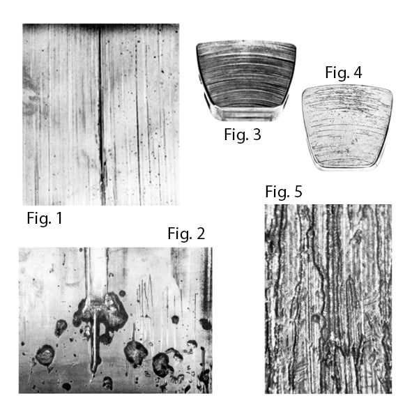
“Dirt” may cause polishing of the surfaces of whitemetal-lined bearings, burnishing of bronze bearings, abrasive wear of overlays or of other bearing linings, and scoring of both bearing and mating surfaces with degrees of severity depending upon the nature and size of the dirt particle, or oil film thickness and type of bearing material.
JOURNAL BEARINGS
Fig. 1 - Whitemetal-lined bearing scored and pitted by “dirt”.
Fig. 2 - Whitemetal-lined bearing showing “haloes” caused by dirt particles.
RECOMMENDED ACTION
● Bearings in condition shown in Fig. 1 should be re-fitted, after cleaning bearings and journal surfaces, provided clearance increase due to wear can be tolerated.
● Bearings in condition shown in Fig. 2 should be scrapped and new bearings fitted after cleaning journal, oil ways and filter (if any) and changing oil.
TILTING PAD THRUST BEARINGS
Fig. 3 - Concentric scoring of thrust pad due to dirt entering bearing at high speed.
Fig. 4 - Scoring of dirt entering bearing at start-up.
Fig. 5 - Surface of pad in Fig. 4 at higher magnification showing irregular tracks caused by rolling of shotblast spherical steel particles.
RECOMMENDED ACTION
● Scrap damaged pads. Clean out lubricating system, change oil and fit new pads.
Under this heading are included:
a) Fretting damage due to inadequate interference fit in flimsy housing.
b) Excessive interference fit causing bearing bore distortion.
c) Effect of joint face stagger or absence of joint face relief in bearing causing overheating and damage in region of bearing
split.
d) Fouling at crankshaft fillets due to incorrect shaft radii.
e) Misalignment or shaft deflection causing uneven wear of bearing.
f) Entrapment of foreign matter between bearing and housing during assembly causing bearing bore distortion and localised overheating.
g) Effect of grinding shaft in wrong direction.
JOURNAL BEARINGS
Fig. 6 - Fretting between back of bearing and housing due to inadequate interference fit. Could also be due to flimsy housing design.
Fig. 7 - Overheating and fatigue at joint faces due to excessive interference fit causing bearing bore distortion. Could also be caused by joint face stagger on assembly or flimsy housing.
Fig. 8 - Fretting at joint faces of connection rod due to inadequate bolt tension.
Fig. 9 - Uneven wear of overlay plated bearing due to misalignment.
Fig. 10 - Fouling between shaft radius and end of bearing, causing overheating.
Fig. 11 - Severe scoring of whitemetal-lined compressor bearing, due to wrong direction of shaft grinding.
Fig. 12 - Back of tin aluminium bearing showing “flat” on steel shell caused by swarf entrapped between shell and housing.
Fig. 13 - Bore of bearing shown in Fig. 12. Entrapped swarf has deformed bearing bore resulting in flexure and fatigue damage.
Fig. 14 - Angular misalignment of shaft or housing, or dirt trapped behind carrier ring, causing damage to pads on one side only.
RECOMMENDED ACTION
● Investigate and if necessary correct
A large dirt particle (probably not less than 1mm across) carried into the clearance space by the lubricating oil, and becoming embedded in the bearing may form a hard scab of material by contact with the steel journal or thrust collar. This scab will then cause very severe damage to the mating steel surface which is literally machined away with the formation of the so-called “wire wool”. The action is self-propagating once started and susceptibility to scab formation appears to depend upon the nature of the lubricant and the composition of the steel of the rotor shaft or collar. Steels containing chromium or manganese in excess of 1% appear to be particularly susceptible to scab formation, especially in high speed machines with bearing surface speeds of over 20 metres per second.
JOURNAL BEARINGS
Fig. 15 - Whitemetal-lined compressor bearing with formation of “Black scab”.
Fig. 16 - 13% chromium steel journal running in bearing shown in Fig. 15 showing severe machining “damage”.
TILTING PAD THRUST BEARINGS
Fig. 17 - “Black Scab” formation on whitemetal-lined thrust pad.
RECOMMENDED ACTION
● Scrap bearings. Pay particular attention to cleanliness during assembly, taking care to avoid contamination of bearing surface and oil ways with swarf etc.
● Investigate possibility of changing journal or collar surface material by sleeving with mild steel, or hard chrome plating.
● Changing the bearing alloy is unlikely to be effective.
● Scrap damaged pads. Clean out lubricating system, change oil and fit new pads.
Corrosion of the lead in copper-lead and lead-bronze alloys, and of lead base whitemetals, may be caused by acidic oil oxidation products formed in service, by ingress of water or coolant liquid into the lubricating oil, or by the decomposition of certain oil additives. Removal of overlays by abrasive wear or scoring by dirt exposes the underlying lead in copper-lead or lead-bronze interlayers to attack, while in severe cases the overlays may be corroded.
JOURNAL BEARINGS
Fig. 18 - Severely corroded surface of unplated copper-lead lined bearing caused by attack of lead phase by acidic oil oxidation products.
Fig. 19 - Fractured section of bearing shown in Fig. 18 indicating depth of corrosion of lead.
Fig. 20 - Corrosion of marine turbine whitemetal bearing. Water in the oil has caused formation of smooth hard black deposit of tin dioxide on surface.
Fig. 21 - “Sulphur corrosion” of phosphor bronze small end bush, caused by decomposition of lubricating oil additive and gross pitting and attack of bearing surface.
RECOMMENDED ACTION
● Scrap bearings. Investigate oil condition to ascertain cause of corrosion. Eliminate water in oil. In case of “sulphur corrosion” change bearing material from phosphor bronze to phosphorous-free alloys such as lead-bronze, silicon bronze or gunmetal after consultation with oil and bearing suppliers.
This is an impact fatigue attack caused by the formation and collapse of vapour bubbles in the oil film under conditions of rapid pressure changes during the crank cycle in internal combustion engines. The harder the bearing material the greater is its resistance to Cavitation Erosion.
JOURNAL BEARINGS
Fig. 22 - Impact cavitation erosion of ungrooved whitemetal-lined bearing occurring downstream of bearing joint face and
groove in the other half.
Fig. 23 - Section through main bearing illustrating mechanism of cavitation and modification to groove to limit or reduce
damage.
Fig. 24 - Discharge cavitation erosion in unloaded half-bearing caused by rapid movement of journal in clearance space during
Crank cycle.
Fig. 25 - Set of diesel engine main bearings showing cavitation erosion of soft overlay while harder tin-aluminium is unattacked.
RECOMMENDED ACTION
● Bearings may be put back into service if cavitation attack is not very severe or extensive. Investigate practicability of increasing oil feed pressure. modifying bearing groove, blending edges or contours to promote streamline flow, reducing running clearance or changing to harder bearing material.
This is caused by the imposition of dynamic loads in excess of the fatigue strength of the bearing material at operating temperature. Fatigue strength, especially of low melting point materials such as whitemetals and lead-base overlays, is greatly reduced at high temperatures, hence overheating alone may cause fatigue failure. Other causes are over-loading, cyclic out-ofbalance
loadings, high cyclic centrifugal loading due to over-speeding, shafts not truly cylindrical due to manufacturing defects such as honing, filing, etc.
JOURNAL BEARINGS
Fig. 26 - Fatigue damage of a new whitemetal-lined bearing caused by uneven journal wear (ridging) in the vicinity of the central oil groove.
Fig. 27 - Fatigue cracking of 20% tin aluminium lining due to misalignment and consequent edge loading.
Fig. 28 - Fatigue cracking of whitemetal-lined bearing due to shaft deflection and edge loading.
Fig. 29 - Whitemetal-lined chambered top half turbine bearing, fatigue cracked on lands due to out of balance loading, and excessively wide cut-away.
RECOMMENDED ACTION
● Scrap bearings. Investigate and, if possible, rectify causes of misalignment, shaft deflection and overloading.
● Increase width of lands in top half Fig. 29. Fit new bearings, possibly of stronger materials if under-design is indicated.
Electrical discharge through the oil film between journal and bearing in electrical machinery, or on the rotors in fans and turbines, may occur due to faulty insulation or earthing or to the build-up of static electricity. This can occur at very low voltages and may cause severe pitting of bearings or journal surfaces, or both. In extreme cases damage may occur very rapidly and the cause is sometimes difficult to diagnose as pitting of the bearing surface is followed ultimately by wiping and failure which may obscure the original pitting.
JOURNAL BEARINGS
Fig. 30 - Fine hemi-spherical pitting and scoring of whitemetal-lined generator bearing due to electrical discharge.
Fig. 31 - Close up of more severe electrical discharge pitting of whitemetal.
RECOMMENDED ACTION
● Scrap bearings if severely pitted or wiped. Examine and, if necessary, re-grind journal to eliminate pitting.
● Investigate earthing conditions of machine especially round any insulation, with particular attention to fittings such as guards, thermocouple leads, water connections, etc., which may be bridging insulation. Fit new bearings and run for only a short time, depending upon the period run to failure point on previous occasion, and examine.
A wiped bearing surface is where surface rubbing, melting and smearing is evident. This is usually due to inadequate running clearance with consequent surface overheating, or may be due to inadequate oil supply, or both these causes.
A wiped surface may follow disruption of the oil film due to extreme loading; and shaft vibrations due to excessive imbalance or journal instability are other causes.
JOURNAL BEARINGS
Fig. 32 - Whitemetal-lined turbine bearing, wiped in both top and bottom halves due to inadequate clearance.
Fig. 33 - Overlay-plated copper lead bearing wiped due to barrelled journal.
RECOMMENDED ACTION
If lightly wiped, re-fit bearing after cleaning surface to remove any loose metal, providing the clearance can be tolerated. If cracked, fit new bearing and increase the clearance when fitting. If vibration present, (a) synchronous with shaft rotational frequency; check balance of rotor, alignment of couplings etc.
(b) vibration frequency at half shaft speed or less; fit anti-whirl bearings.
TILTING PAD THRUST BEARINGS
Fig. 34 - Surface wiping of whitemetal-lined pad, in successive thin layers, due to excessive steady load at start-up.
RECOMMENDED ACTION
● Fit new pads. Improve lubrication at start-up, possibly by using jacking oil system. If possible reduce loading at start-up.
This may be due to inadequate oil pump capacity, inadequate oil gallery or oilway diameters, incorrect grooving design, accidental blockage or cessation of oil supply. In the case of machines depending only upon shaft driven lubricating oil pumps, it may be due to inadequate oil supply during starting up - perhaps due to failure to operate hand priming pumps in an adequate manner. Depending upon the duration and severity of the lubrication failure, surface melting and wiping, or complete seizure of the bearing may occur.
JOURNAL BEARINGS
Fig. 35 - Fatigue cracking caused by inadequate lubrication due to axial grooving in loaded area.
Fig. 36 - Overheating and damage of tin aluminium bearing surface due to reduced oil flow caused by sealed cavity with no drain hole at one end of bearing.
Fig. 37 - Seizure of 20% tin aluminium bearing due to lubrication failure.
RECOMMENDED ACTION
● Investigate and, if necessary, correct groove design. Investigate lubrication conditions. Scrap bearings. Examine and, in cases of seizure, crack detect journals. Fit new bearings.
The damage illustrated is fretting damage in the bore as distinct from fretting damage elsewhere. Bearing operating surfaces may suffer fretting damage while the shaft is at rest due to vibrations transmitted to the machine from external sources, etc.
JOURNAL BEARINGS
Fig. 38 - Surface damage caused by external vibration while journal was not rotating.
RECOMMENDED ACTION
● Eliminate transmission of vibration from external sources if feasible by spring or rubber -mounting affected machine. If damage occurs in transit, clamp journal to prevent vibration during shipment, or fit dummy wooden bearings during transportation.
Lining extrusion and cracking may be due to overheating with consequent reduction in strength of linings so that the material yields and cracks due to the effect of normal and shear forces transmitted through very thin oil films. Wiping does not necessarily occur under such conditions. Surface deformation can be caused in an anisotropic material by thermal cycling.
TILTING PAD THRUST BEARINGS
Fig. 39 - Cracking of whitemetal lining pad due to operation at excessively high temperatures. Note displacement of whitemetal over edge of pad due to extrusion.
Fig. 40 - Cracking and displacement of whitemetal lining of pad due to overheating under steady load conditions.
Fig. 41 - Thermal “ratchetting” of whitemetal lining of pad due to thermal cycling through excessive temperature range in service.
RECOMMENDED ACTION
● Investigate and if possible reduce maximum operating temperatures. Fit new or reconditioned pads.
Axial vibration can cause damage and fatigue of tilting pad pivots, both pivot and carrier ring suffering damage by indentation or fretting. In some cases tiny cavities of almost hemispherical form may be produced. Damage may occur due to axial vibration imposed upon the journal, or may be caused by thrust collar face running out of true.
TILTING PAD THRUST BEARINGS
Fig. 42 - Pad carrier ring showing damage due to axial shaft vibrations.
Fig. 43 - Pad pivot showing hemispherical cavities caused by pivot fretting due to vibration.
RECOMMENDED ACTION
● Recondition carrier ring, and fit new or reconditioned pads. Investigate and eliminate cause of axial vibration.
AI Website Software